Spine Without Instrumentation
Welcome to Dr Khurana’s Spondylosis page.
Images shown here are with the permission of Dr Khurana’s patients, for educational purposes.
Click any image for a larger view
-
- Image 1
-
- Image 2
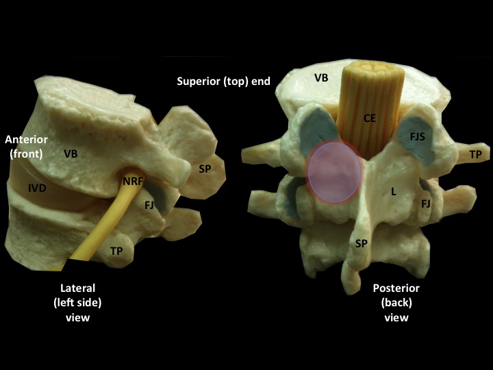
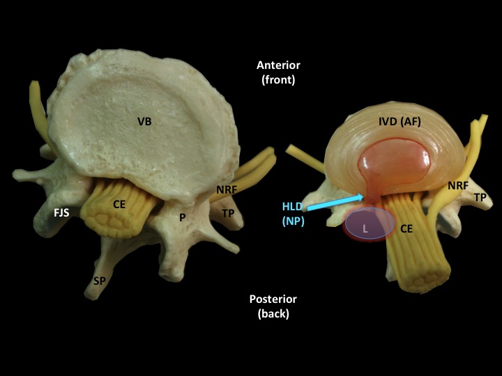
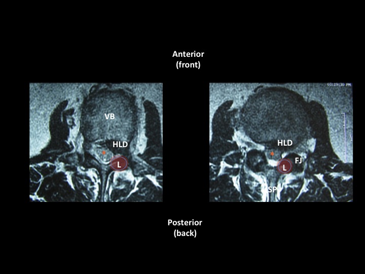
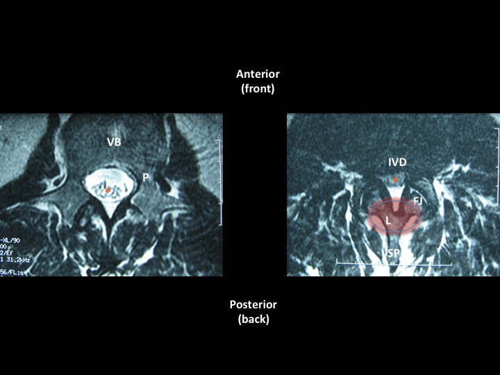
Images 1 & 2a (above left and right) show basic spinal structure/anatomy.
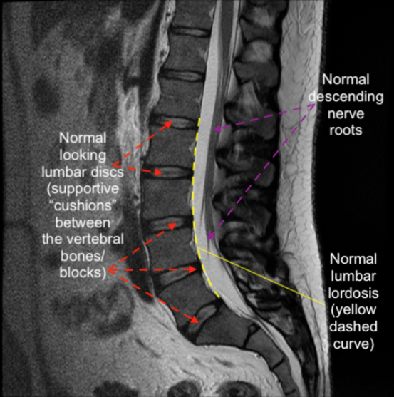
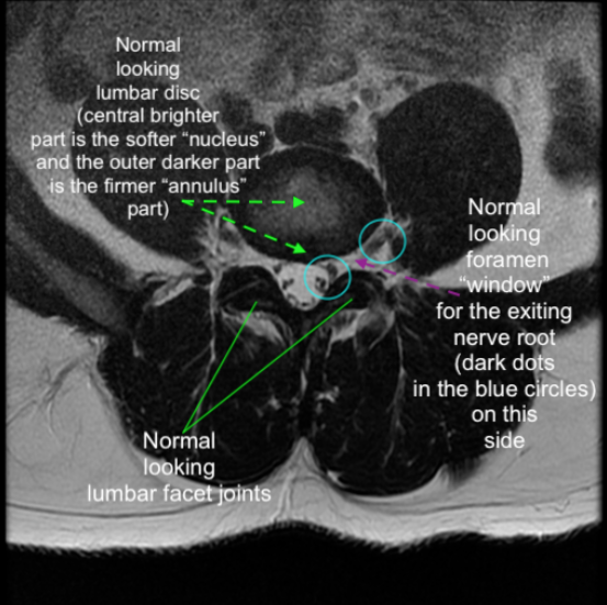
Images 2a & 2b (above left and right) show normal lumbar spinal structure/anatomy on an MRI (T2 seq.)
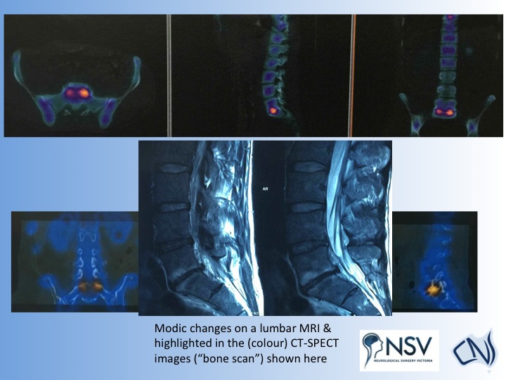
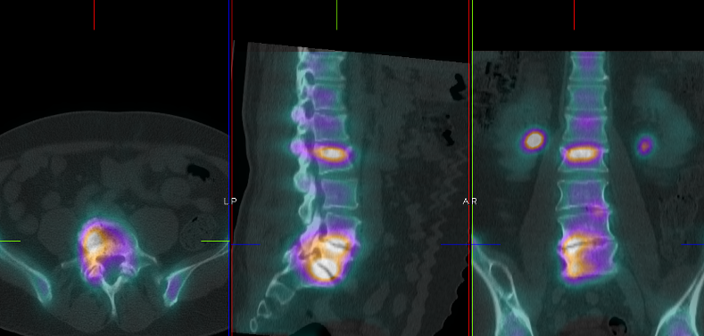
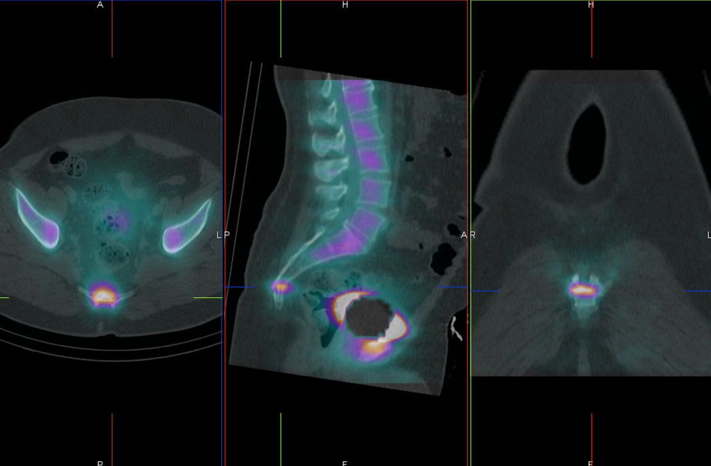
Image 3 (above and below) shows areas of active spine degeneration/spondylosis (depicted brightly in yellow/orange here) on a CT-SPECT “bone” scan. The “bone scan” is a very helpful and sensitive scan using a combination of low-dose CT scanning and a safe, dilute radio-tracer to find “hot spots” in the bones and joints. Such “hot spots” could be inflammation, deposits of tumour/cancer, infection, trauma, or sites of active degeneration. They “light up like a bulb”.
In the CT SPECT/bone scan shown below, there is a wedge fracture at L2 of little clinical relevance. The patient’s discs at L4/5 and L5/S1 were very worn/degenerative, and the are lighting up on the bone scan images. The discs were successfully replaced by me shortly after the scan was done, and the patient has gone on to resume a very active and independent life again.
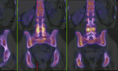
Facet joint stress/inflammation and degeneration shown below
Thoracic wedge compression fracture shown below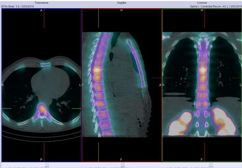
Isolated cervical facet arthritis shown below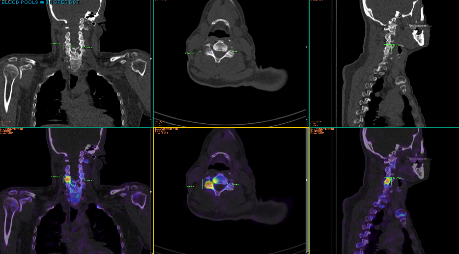
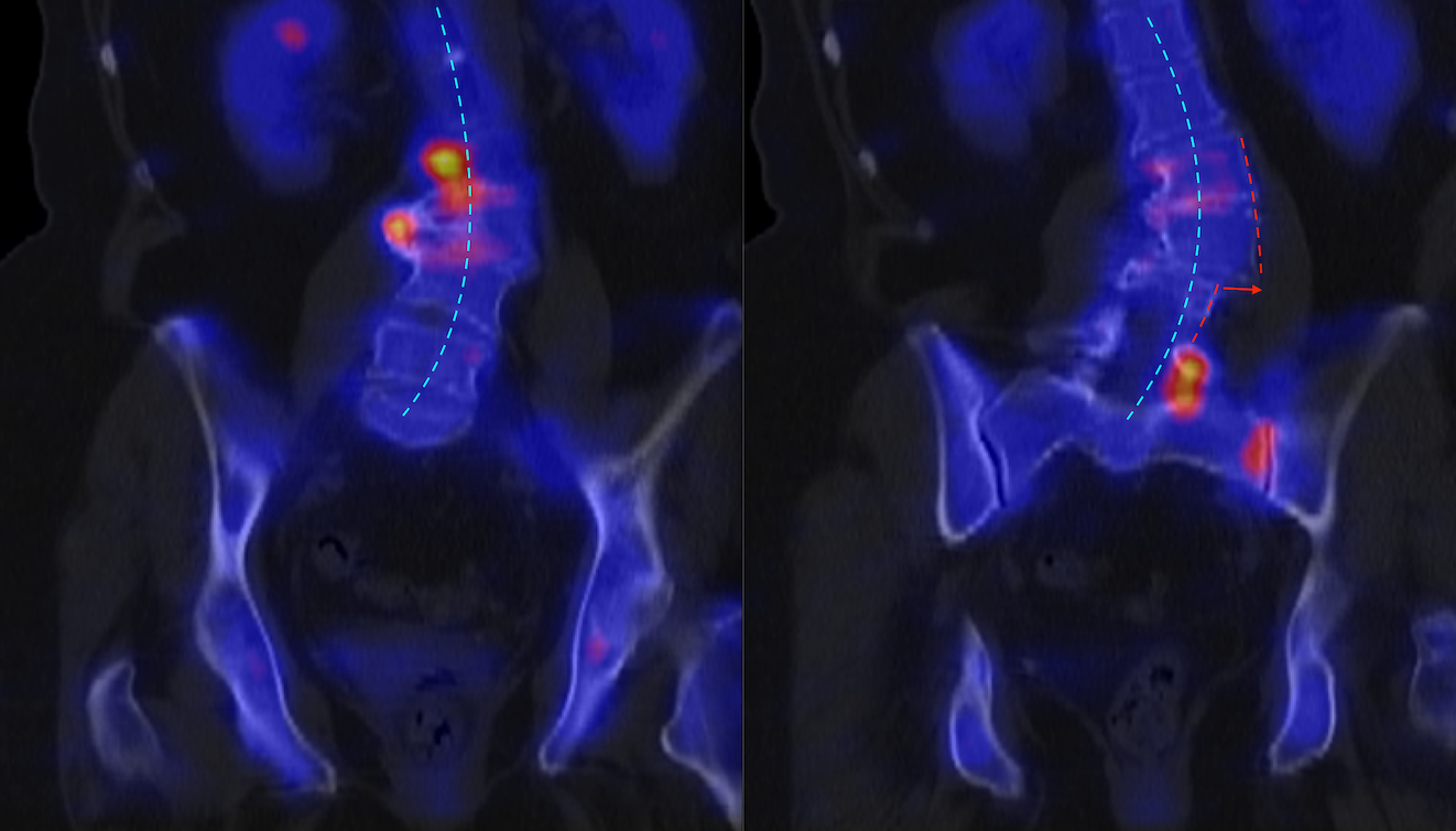
Shown below: Degenerative scoliosis and “hot spot” “stress points” at discovertebral, osteophyte spurs, facets, and SI joint. At the curvature/ inflection point, note there is also additional lateral slip / listhesis (red arrow between dashed red lines). I referred her to a scoliosis surgeon.
-
- Image 4
-
- Image 5
-
- Image 6
-
- Image 7
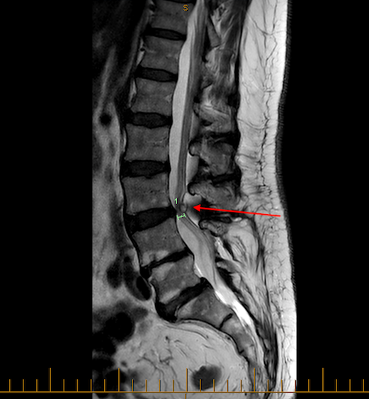
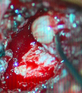 Image 6b
 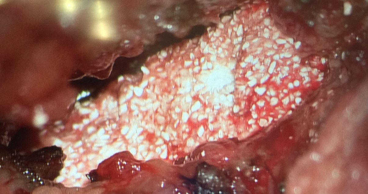 Image 6c
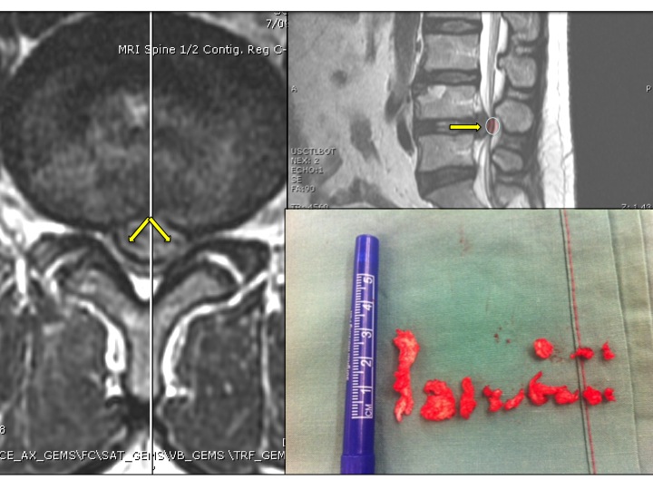
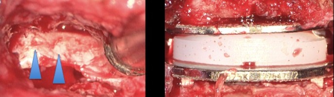
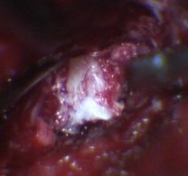
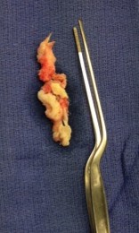
The intra-operative colour-picture immediately above (Image 6b, left) shows part of another patient’s complex synovial cyst being removed. A posterolateral non-instrumented fusion (e.g., using iFACTOR bone-forming matrix; Image 6c, above right) can be carried out at the end of a synovial cyst excision surgery, to aid the mechanical stability of the joint from which the cyst arose and was removed. In combination with temporary back bracing, the fusion material should form a solid bone bridge in time, increasing local bone stability. During this time of “fusion” which can take up to 12 months to occur, Dr Khurana recommends oral supplementation of Calcium and Vitamin D, and permanently not smoking.
Image 6c
The intra-operative colour-picture immediately above (Image 6b, left) shows part of another patient’s complex synovial cyst being removed. A posterolateral non-instrumented fusion (e.g., using iFACTOR bone-forming matrix; Image 6c, above right) can be carried out at the end of a synovial cyst excision surgery, to aid the mechanical stability of the joint from which the cyst arose and was removed. In combination with temporary back bracing, the fusion material should form a solid bone bridge in time, increasing local bone stability. During this time of “fusion” which can take up to 12 months to occur, Dr Khurana recommends oral supplementation of Calcium and Vitamin D, and permanently not smoking.
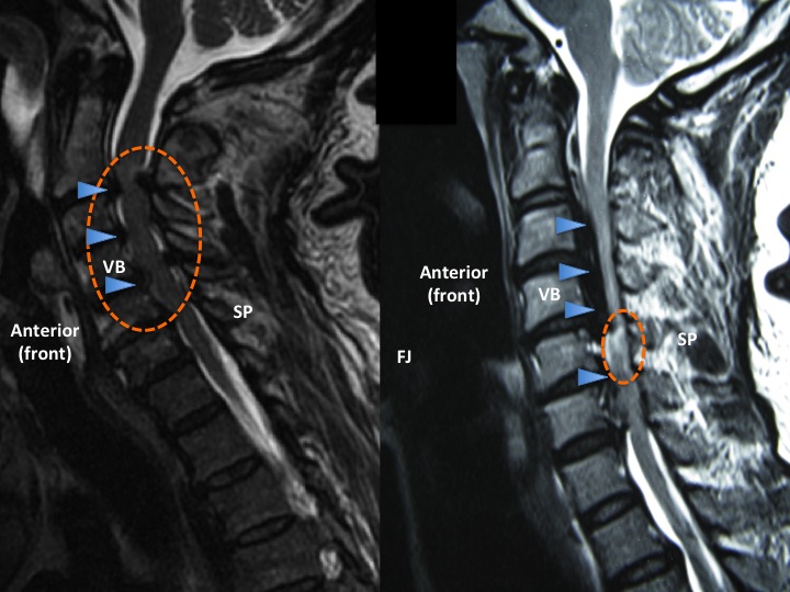 Image 8
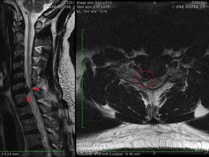
Compression of nerve tissue can also occur over time in the cervical spine. Examples of patients who presented with cervical myelopathy from cervical spondylosis (left panel of MRI, Image 8, above) and ossification of the posterior longitudinal ligament (OPLL, right panel of MRI, Image 8, above) are shown here.
Image 8
Compression of nerve tissue can also occur over time in the cervical spine. Examples of patients who presented with cervical myelopathy from cervical spondylosis (left panel of MRI, Image 8, above) and ossification of the posterior longitudinal ligament (OPLL, right panel of MRI, Image 8, above) are shown here.
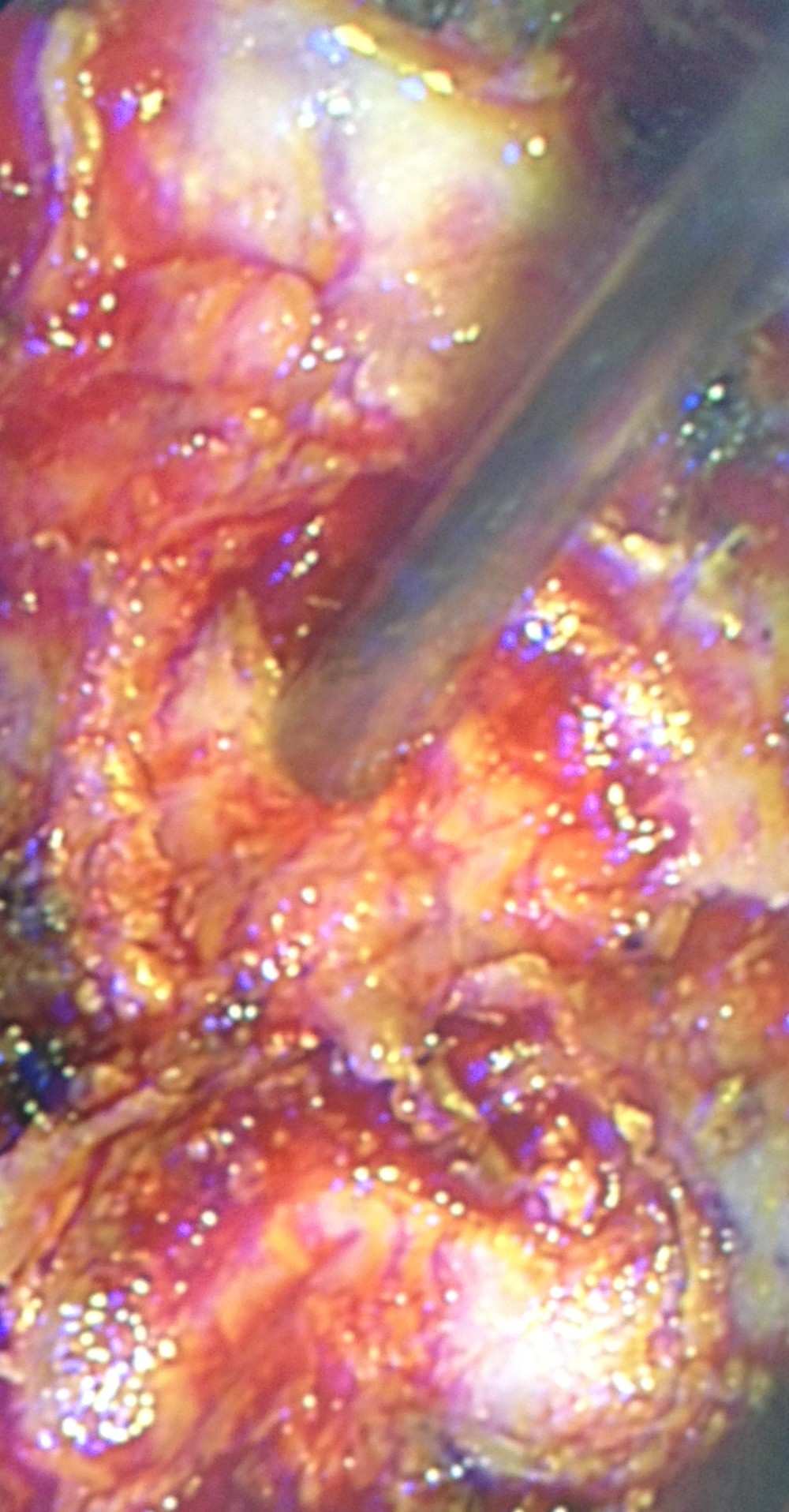
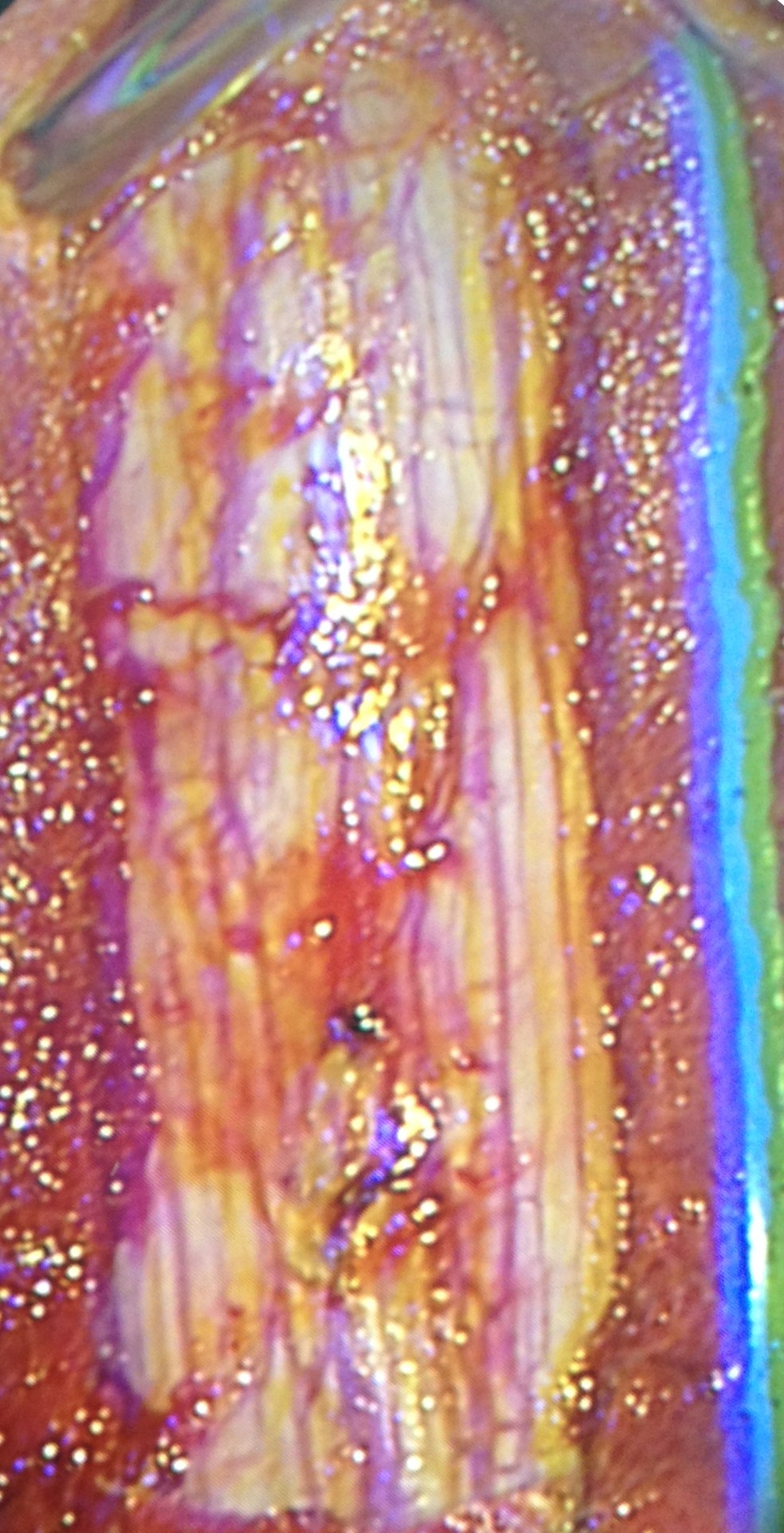 Images 9a and b
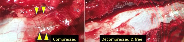
Images 9a (before) and b (after) shown here are intraoperative from a patient undergoing cervical decompressive laminectomy and rhizolysis (C3-6 inclusive in this patient). No more compression of the spinal cord!
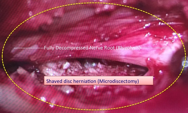
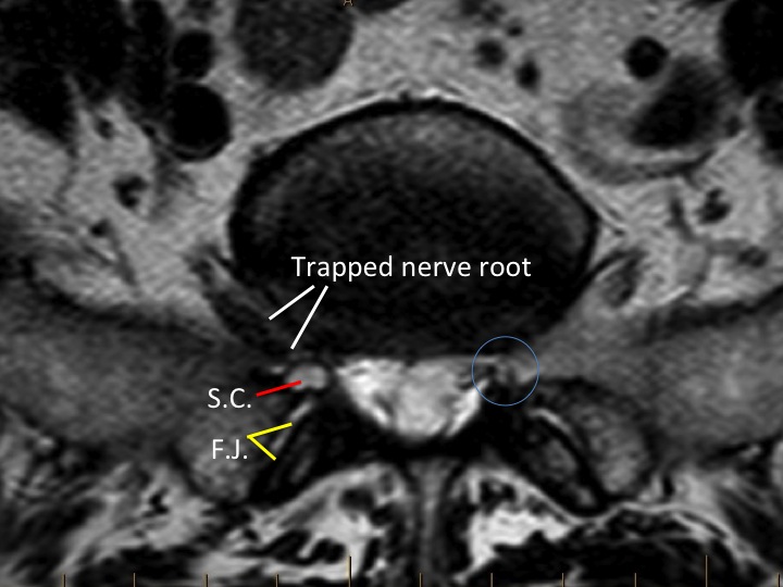
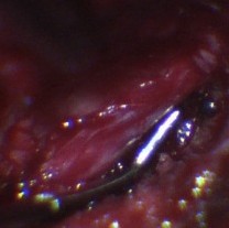
Image 10 (above) is an intraoperative image of a surgically decompressed lumbar nerve root which had previously been compressed by a combination of disc bulge and overgrown ligament and facet joint tissue. The surgical incision required to do this surgery is quite tiny using minimally invasive techniques.
-
- Image 14
-
- Image 15
-
- Image 16
-
- Image 17
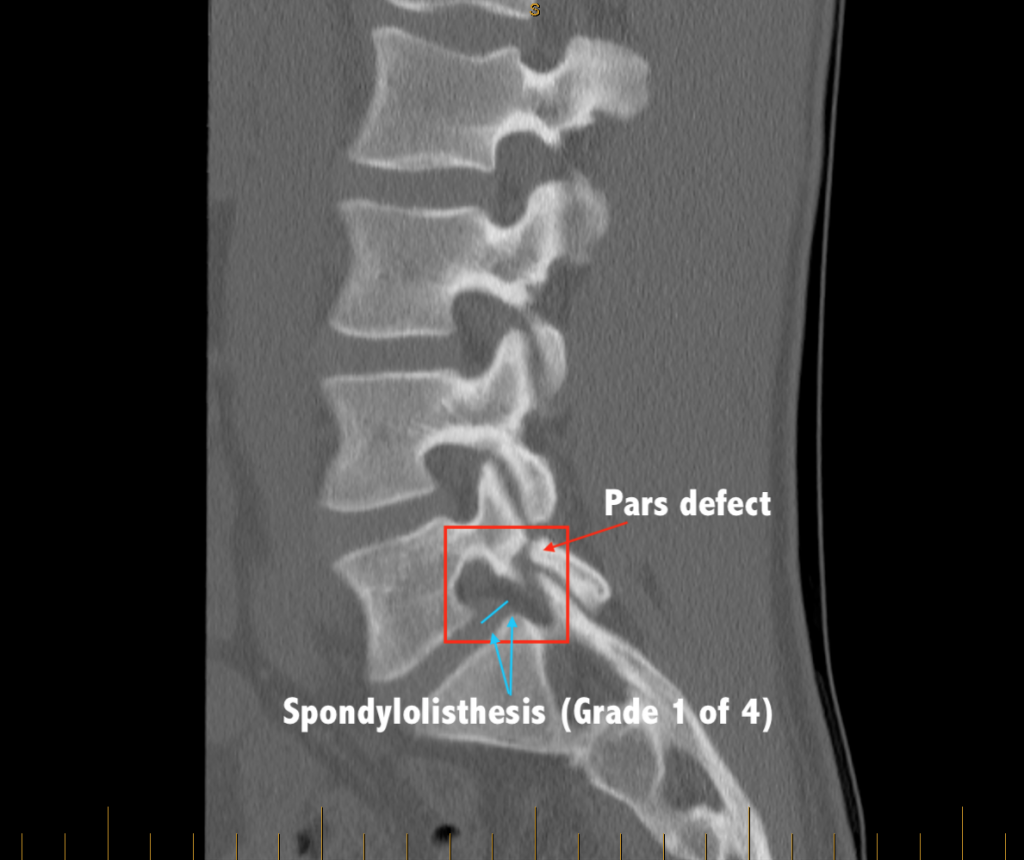 Image 19 (below) shows an even worse “slip” (Meyerding Grade 2 of 4) from a congenital pars defect.
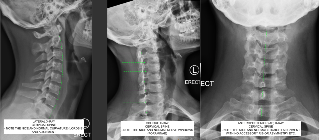
 Image 20 (below) shows a normal “cervical spine series” set of x-rays from a young healthy and active adult.